All the parts for the 68komputer came in, so it’s time to crack open a cold one, fire up the soldering iron, and curse whatever idiot designed this board.
Assembly
Aside from decoupling and a few resistors, basically everything on this board was socketed and through hole, which made assembly pretty easy. The resistors/capacitors are 0805 size, which wasn’t much of a problem for me despite being seriously out of practice – I guess part of the thanks goes to the Hakko FX-888D I recently added to my toolset: it’s definitely worth the $125 or so one will run you from an authorized reseller.
I started off by soldering all surface mount components on the bottom side of the board. While putting a lot of the decoupling capacitors on the bottom side helped simplify routing and layout, it did make assembly a bit more annoying, especially since I neglected to add screw holes that standoffs could mount to, meaning the board will never sit flat on a surface now.
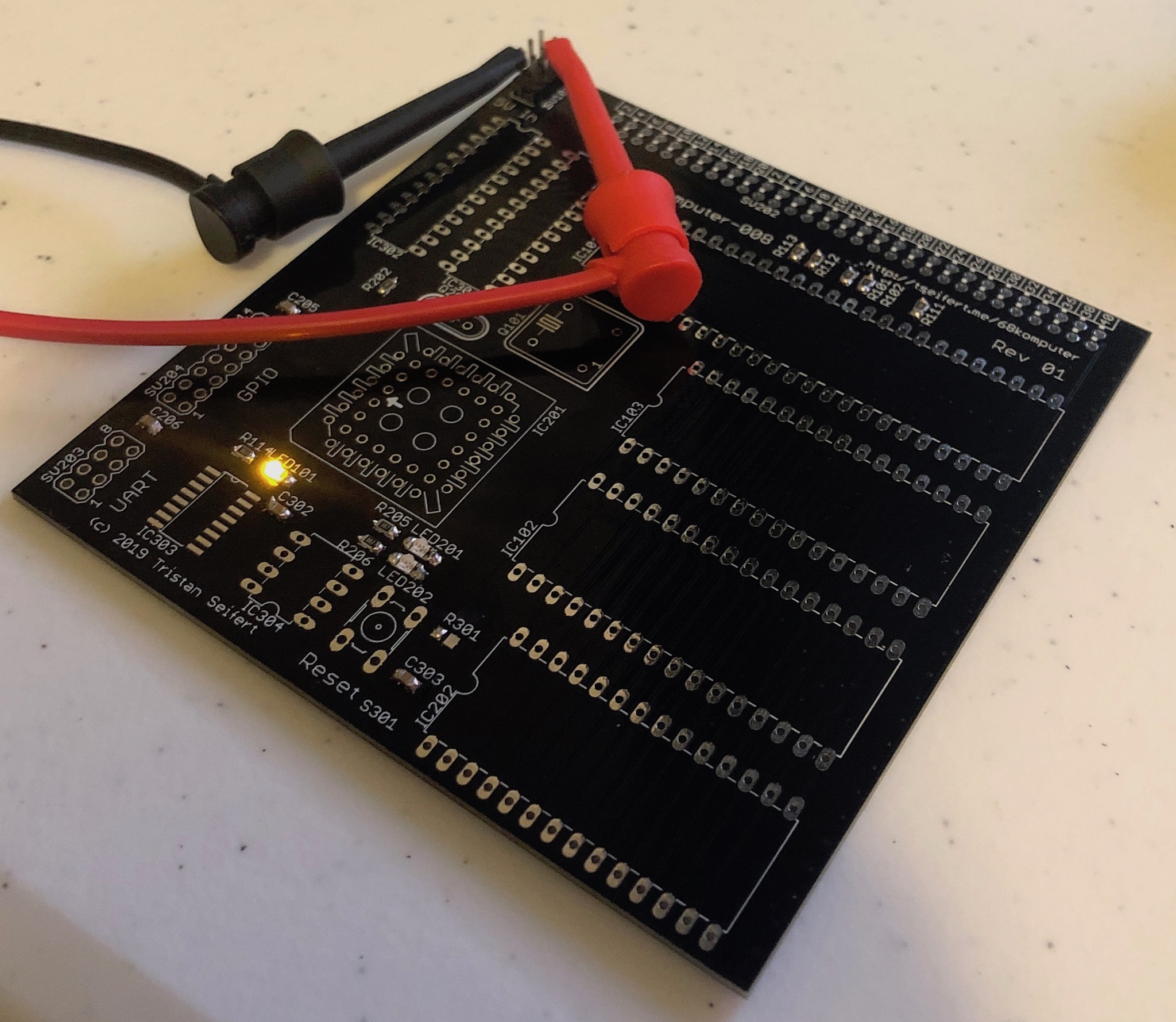
Next up I took care of all surface mount stuff on the top side, which was a lot easier to solder due to not having any of the big tantalum capacitors. Once I finished the top, I soldered in the +5V In headers, and hooked the whole thing up to a power supply. This was a good test to at least verify there’s no short circuits in the power distribution, and let me probe that I had +5V on all pins that called for it.
You might notice that there’s a resistor and IC missing (R301 and IC303 for those playing along at home,) but I just said that all surface mount components were populated. The IC was completely missing a Mouser part number in the schematic, while R301 (and another resistor on the bottom) had the wrong part number – I got 18.3 ohm resistors, instead of the 1M ohm resistors the 555 reset circuit called for. (I later bodged in some through-hole resistors, but it’s not pretty so we’re going to pretend I didn’t do that.)
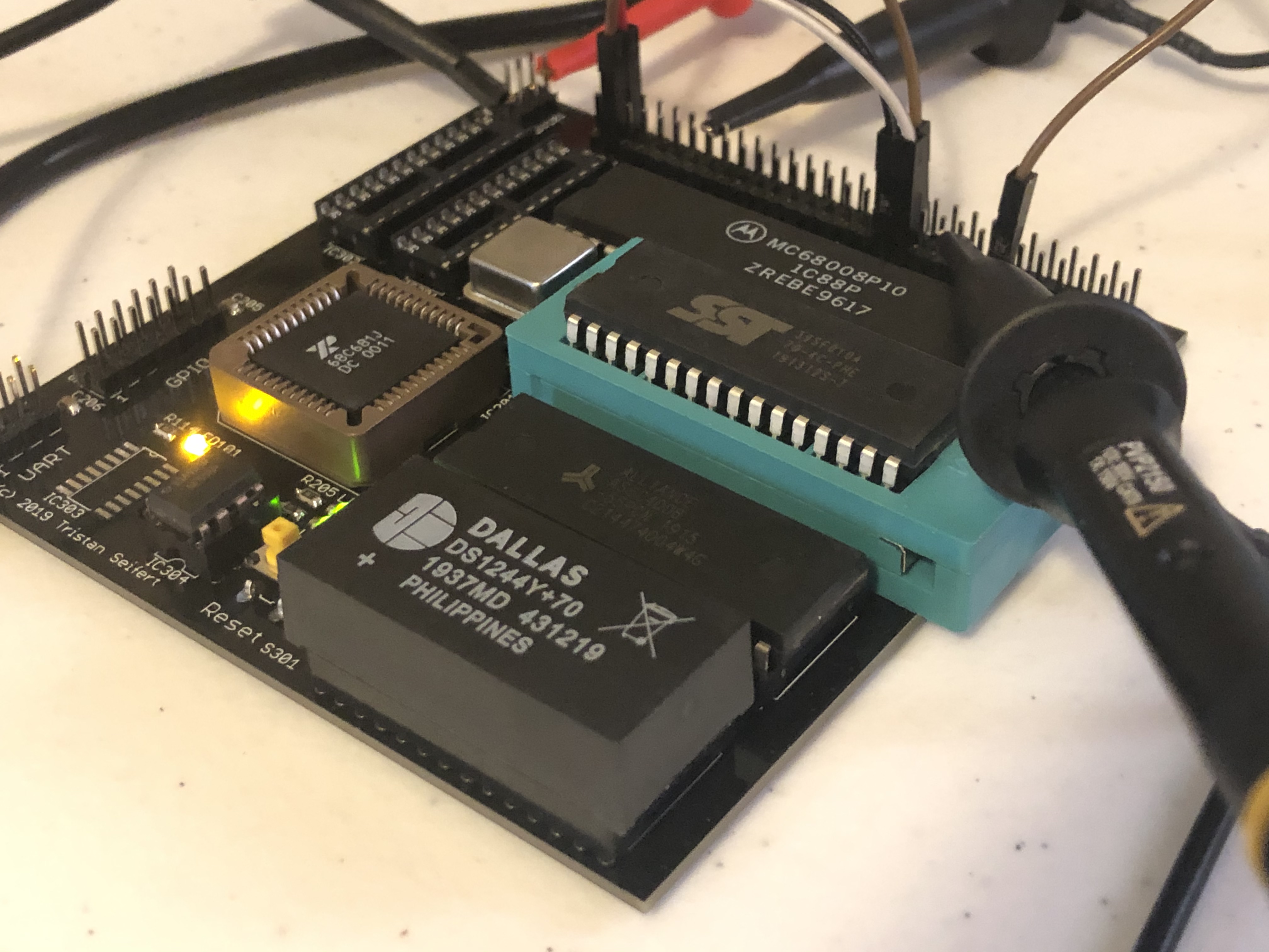
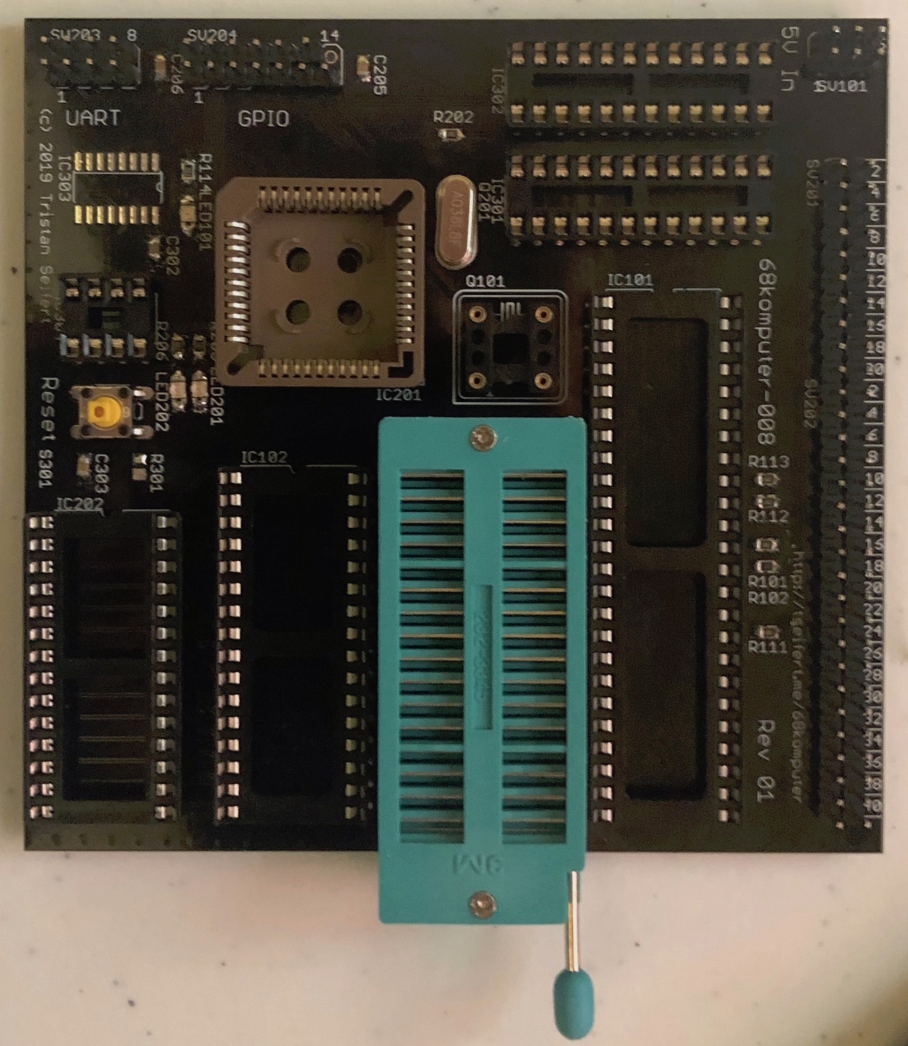
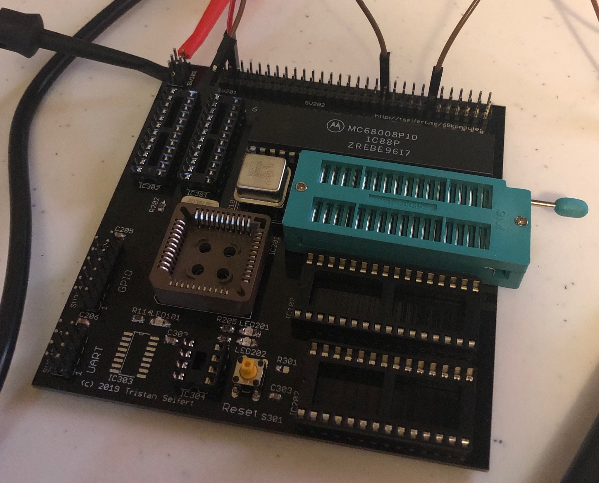
Last up were all of the remaining through-hole components on the top side. This includes the rest of the connectors, sockets for all ICs, the reset switch, and the crystal for the 68681. I planned on just using a regular socket for the ROM (IC103,) I was able to get a few very nice ZIF sockets pretty cheap, and thankfully, was able to fit one on the board. It’s definitely a very tight fit, it hangs off the edge of the board, and it’s backwards, but it should make reflashing the ROM much less of an adventure.
Testing
The board is fully assembled, so it’s time to test a few things before I go ahead and install all of the ICs. I wanted to be absolutely sure I wasn’t going to release any magic smoke before I shoved any of my precious ICs into their sockets. The first test was just sticking the oscillator into its socket at Q101.
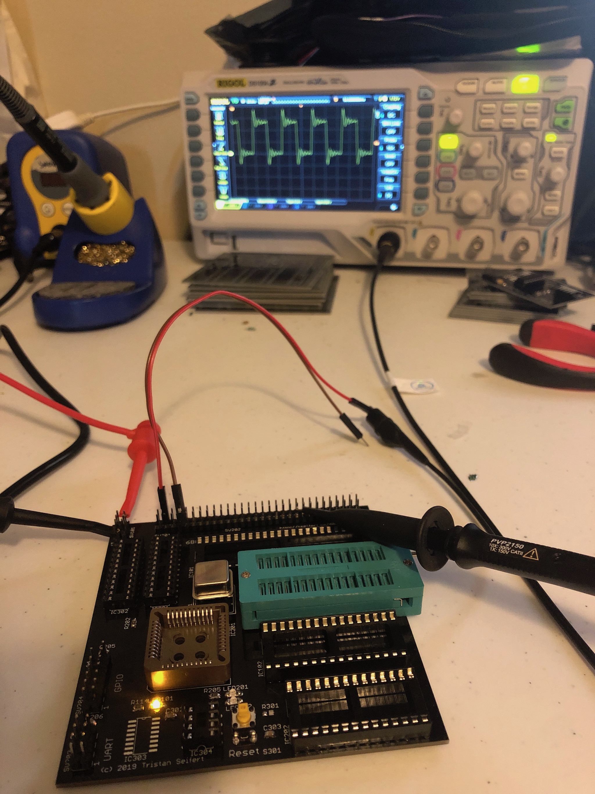
Thankfully, the first time I switched the power on I saw the 8MHz clock signal I expected on my scope, along with the (basically nonexistent) current draw I expected, which was a good sign.
Free Running
Next up, I put the 68008 in its socket at the top of the board, and grounded the DTACK pin (with the brown wire) so that the CPU would free run. Since the data bus is pulled down, the CPU will read $00 over and over again, which is (essentially) a no-op: it’s the opcode for ORI.B #0, D0.
Then, since I didn’t feel like connecting this whole thing to my logic analyzer just yet, I connected a second probe on my scope to one of the address lines. Theoretically, since we’re not inserting any wait states (remember, DTACK is grounded,) A0 should toggle every 4 clocks; for any address line An, the period will be $P_n = 2^{n+2}$ clocks.
At first, I saw no activity on the address line, or any of the CPU’s status lines. After a bit of fiddling with the reset circuitry (since the 555 did not work without the 1M resistors), I simply grounded both HALT and RESET simultaneously to put the chip into reset. That’s all it took to get the address line to toggle – turns out the user manual wasn’t lying when it said a PoR circuit is mandatory.
In the future, I will probably replace that troublesome 555 PoR circuit with a device like the LM3723. This device outputs a nice ~100ms reset pulse whenever the external reset input is asserted, and will hold its reset output asserted so long as the voltage rails are out of spec.
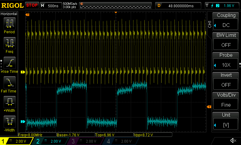
The yellow trace is the 8MHz clock, while the light blue trace is A1. If you look closely, you can see that A1 toggles every 8 cycles of the system clock (or every 1µS/two horizontal divisions) which is exactly what the output should be. The signals are definitely bit noisy, but that’s most likely just an artifact of the crappy grounds I have connected to the scope probes for this quick and dirty testing.
Once I bodged in some 1M resistors for the 555, the reset button itself worked, but the power-on reset simply did not work right or reliably enough – you have to hit the reset button every time the machine is turned on. This is yet another reason that revision 2 will have a dedicated part to handle resets.
A Note on Counterfeit Parts
Unfortunately, this is where I had to put the project on hold for a bit – thanks to College Station’s horribly incompetent post office, I’ve been waiting for over a week for the GALs I ordered off eBay to show up. Without those, there’s no glue logic in the system. No glue logic means no address decoding, so I can’t do much beyond free running the chip.
When those parts eventually showed up, I was pretty displeased to discover that I could not get the GALs to program. Nothing I tried would get the logic to actually stick: usually I’d be greeted by an over-current error from my programmer, or verification would fail. I ended up ordering some more GAL22V10’s from a different seller, which (thankfully) arrived in only 3 days. Those were able to be programmed, and would verify ok.
I’m still not really sure why that first batch of chips didn’t work. I’m pretty sure that they were counterfeit or different chips relabeled as GAL22V10’s, because the odds of all 25 in the tube I ordered being dead seemed rather unlikely to me. Lesson learned: don’t buy parts you expect to work from China, however good the price may seem.
It Lives… Almost
With working GALs finally here, I proceeded to compile the logic equations, which I had written in CUPL, and compiled with the (absolutely god-awful) WinCUPL tool from Atmel. I’ve had a few weeks to stare at those equations, so I figured that they’d be correct, and would just… work. (Famous last words?)
So, I programmed the two GALs the system calls for, slammed them into their sockets, turned on the power, and hit the reset button, expecting to see my monitor ROM’s prompt showing up on my VT320… but nothing. No serial outputs, no blinking LEDs, nothing. Oops. Immediately I focused on somehow verifying that the GALs did what I expected them to. I did this for a bit by connecting inputs to either GND or VCC, and watching the outputs on some LEDs – but fiddling with tiny wires sucks!
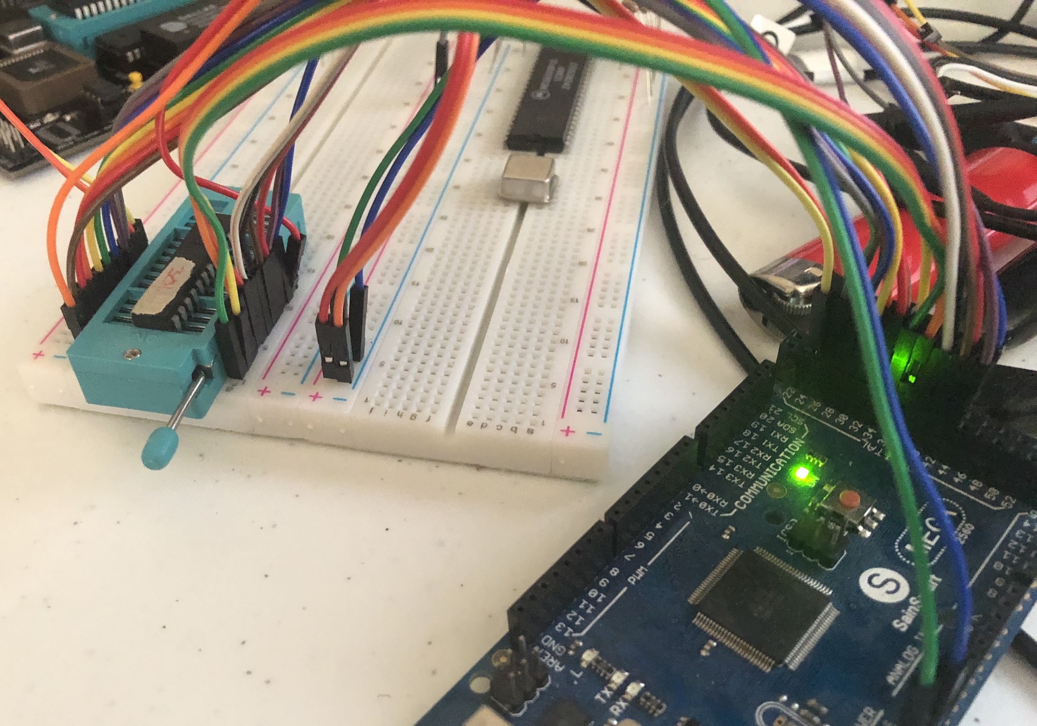
Thankfully, my big pile of random boards contained an Arduino Mega, which has enough GPIO pins to connect to every pin on the GAL without needing to use port expanders or shift registers, which made programming significantly easier. For convenience, I threw a ZIF socket on the breadboard as well.
The sketch running on the Arduino is pretty simple. It doesn’t attempt to emulate timings (which shouldn’t really matter, since the GAL is a 15ns part anyways) but instead simulates a 68k bus cycle for a given address. It then prints out the states of chip selects, strobes, and so forth, which pretty quickly revealed a problem: the OE signal was inverted from what it should actually be.
Fixing that proved to take nothing more than adding a single exclamation mark… meh. But now the GAL’s outputs made sense, and it passed the tests I had for it. There was just one more test: would the machine boot with it?
It’s Alive
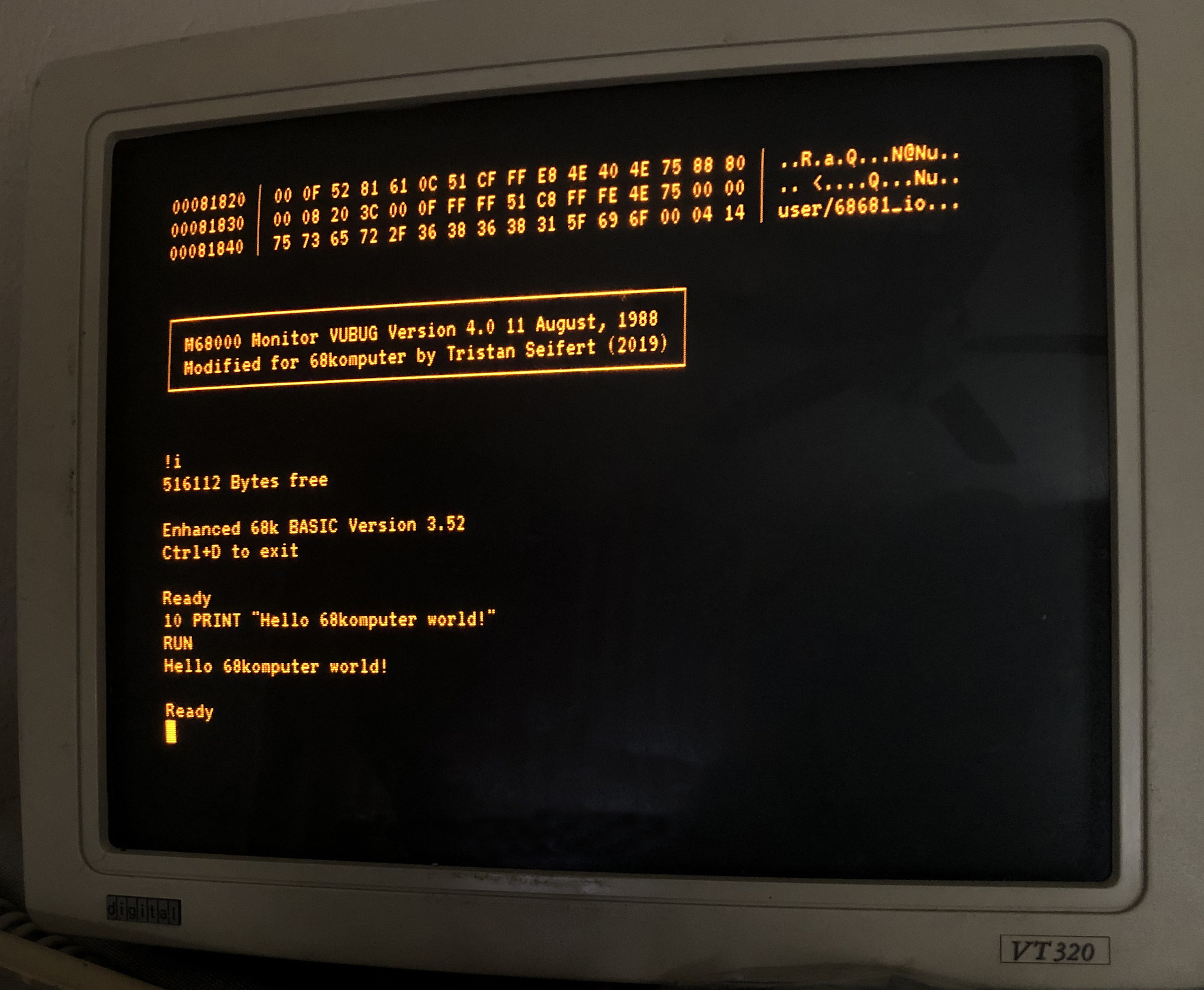
Once that logic bug was squashed, the GAL went back into its home on the board, and, much to my surprise, the machine actually booted right into the boot ROM monitor after I hit the reset key. On one hand, this wasn’t super surprising since I had a lot of confidence in the software (after all, I tested it on the absolute abomination of an emulator that I glued together,) but this was my first project with technology that’s twice as old as I am, so there was a lot of learning and uncertainty about the actual hardware.
The monitor does pretty standard “monitor things,” namely letting you dump or modify memory, load programs over the second serial port, and even produce a disassembly listing – it’s based on a version of the VUBUG monitor that’s been around for probably as long as the 68000 itself has. It wasn’t super difficult to modify the code for this machine, since platform-specific things like character IO were nicely abstracted out into their own subroutines.
But what good is any 80s-era computer design without a BASIC interpreter in ROM? None at all! Since the ROM is a whole 128K, and the monitor took up maybe the first 16K of it, I had plenty of space for such luxuries. For this machine, I have Lee Davison’s Enhanced Basic in ROM.
Conclusion
That’s where I’m at with this machine right now. It’s been quote a journey over the past few months designing, and finally building it, and having it actually sit in front of me, fully functional, is awesome. It doesn’t do a whole lot yet, but I can easily load code via the serial port, which means I’ll be able to focus on writing software.
However, this project is nowhere near finished – not that I’ll ever finish a project in my life – there’s still plenty to be done. The board could definitely use a second revision, if only to clean it up a little, simplify assembly, and fix some minor issues, including the reset circuitry. I also still haven’t built the bus timeout circuit, but I see no reason why it shouldn’t work. (Ironically enough, the missing DS line on the GALs makes zero difference to the operation of the machine; indivisible bus cycles won’t work right… but that just means the TAS instruction doesn’t work.)
To-Do List
All major components of the machine work properly: both serial channels and their IOs operate correctly, all 512K of RAM pass tests, and data is correctly persisted in the NVRAM/clock chip. However, the ROM toolbox routines to interact with the hardware are buggy at best, and outright garbage at worst. I’ll need to get those in a semi-useable form before I can go ahead and start writing serious software for this machine.
Beyond that, next up is building a sort of expansion backplane that connects to the big 60 pin expansion header. I have the designs for this backplane essentially finalized, as well as for a sound board that includes a YM3812, an AY-3-8910, and an UART dedicated to a set of MIDI input/output connectors: I figured being able to use this thing as a self-contained synthesizer would be pretty cool. (I was hoping to use the DUART for MIDI, but it’s not able to get the 31,250 baud speed with its crystal.)
Eventually, I’m going to take this design and update it to use a full 68000: this shouldn’t be too bad, considering that this design is proven to work. In theory (again… famous last words,) it would just add another 8 bits of data lines, and replace the single DS signal with UDS and LDS. Fitting two ZIF sockets for the ROMs is probably going to end up being the most difficult part. 🙃
Sources
As with most my projects, the latest versions of the hardware and software are available on GitHub.
Schematics and board layouts are done in Autodesk EAGLE – eventually, I’ll get around to learning KiCad, but while I’ve still got access to my University’s site license, I’m enjoying every bit of it: especially considering I’ve been using EAGLE for years, and am pretty attached to its way of doing things.
GAL logic equations are written in CUPL, since these devices are so old that there’s no Verilog compilers for them. Unfortunately, this also means that there’s no getting around using Windows to compile it, since WinCUPL just does not run under wine: not to mention that macOS 10.15 removed the ability to run 32-bit applications anyways.
The boot ROM and hardware routines are all written in good ol 68000 assembly. The code is targeted to use the vasm assembler, which is open-source and runs on just about everything. Aside from vasm, the build scripts rely on standard tools available on any machine worth using.